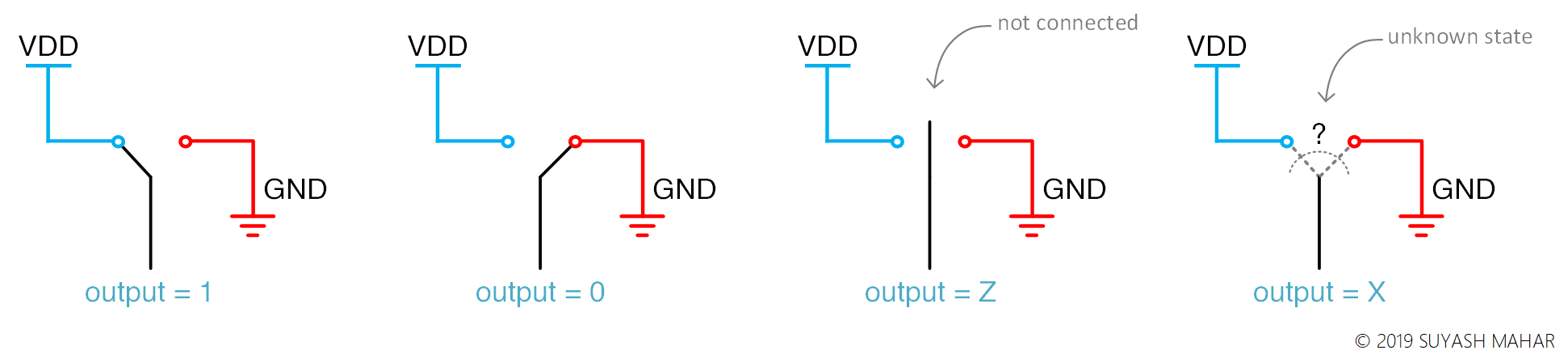
The Verilog standard defines a value set with four different values
for you to use. You can have these values read out from either to a
net (wire) or a variable (reg) type. Here are those values:
| Value | Description |
|---|---|
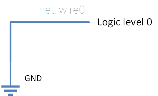
| 0 | Logic level 0 |
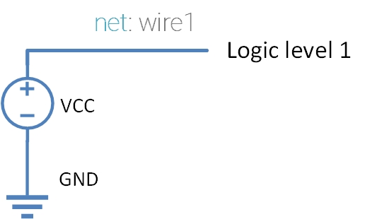
| 1 | Logic level 1 |
| X | Unknown value |
| Z | High Impedance |
Every Verilog data type allows storing all of these values (⚠:️ There are some exceptions).
The logic level values (1 and 0) are easy to understand; they
represent the binary values 1 and 0, respectively. We’ll briefly
discuss them, just enough to lay the groundwork for the more
interesting ones, the X and Z.
Description and Working
Logic Level 0: 0
The logic level 0 represent a logical 0 or a false value. In
most of the cases logic level 0 represents a voltage level of 0 volts
(or ground). We’ll follow this convention for the purpose of
simplicity.
Logic Level 1: 1
Logical value 1 represents the logical complement of logic level 0.
\[1 = \text{True} = \overline{0}\]Logic level 1 as per our convention will represent the supply voltage (VCC or VDD).
Unknown Value: X
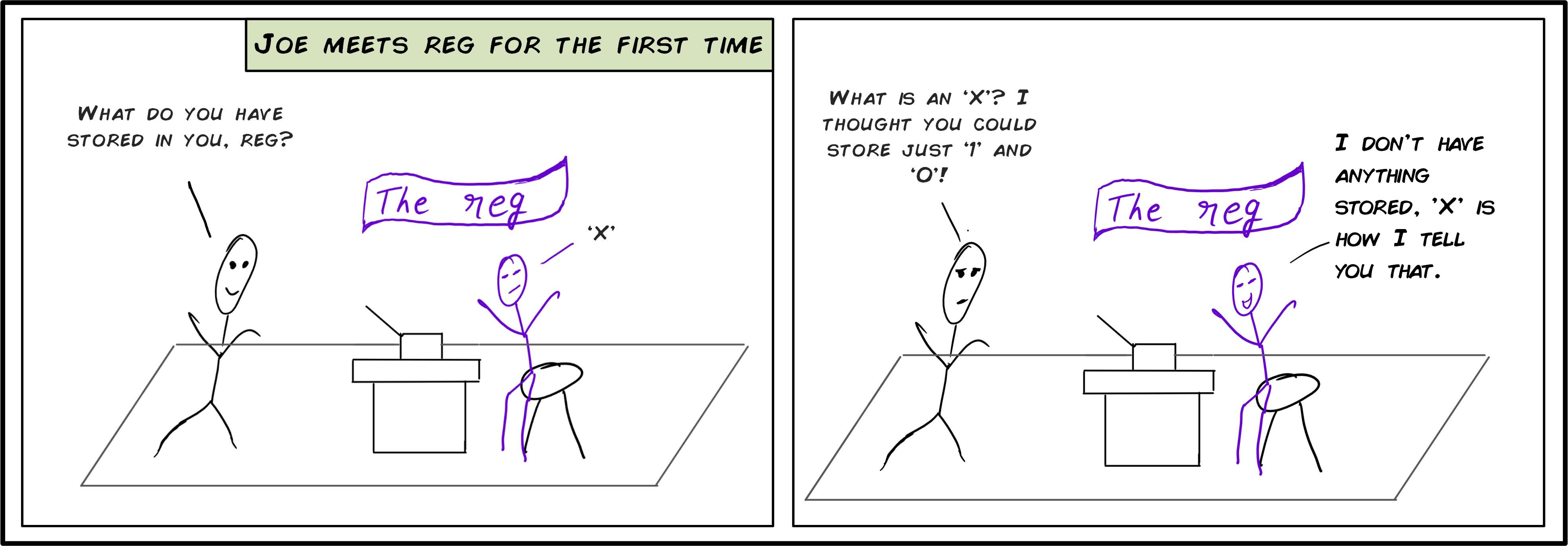
When Verilog cannot decide the output logic level of a net or a variable, the output would be set to ‘X’. Say, for example, you have a reg, and you didn’t specify the default value or set it during runtime. In that case, the hardware wouldn’t know what it should output. What Verilog does to represents this scenario is to tell you that the wire could have either 1 or 0, by using the value ‘X’.
A different point of view for the same thing is saying that the net or reg value can either be 0 or 1, but we don’t know which one of them it is.
Few example use of unkown value is:
- Case statements: matching multiple values in a case statement
always @(some_signal) begin
    select @(other_signal) begin
        case 5'b0000x: begin
            // Selects the case 5'b00000 and 5'b00001
        end
        case 5'b1111x: begin
            // Selects the case 5'b11110 and 5'b11111
        end
        default: begin
            // All the other cases
        end
    endcase
end
High Impedance: Z
Before understanding what high impedance value in Verilog is, it is important to understand what high impedance means in real-life electronics. High impedance state is often used in digital circuits/electronics to refer to an output which cannot drive any other input (i.e., an open circuit). Say, for example, a wire which is unconnected at one end is used as input to a gate. Now, to the gate that input would appear as an open circuit, or a circuit with infinite resistance. This is what the electrical engineers call a high-impedance state.
So, in verilog whenever you have a net type or a variable type which isn’t being driven (connected to some output for net type and holds a ‘Z’ value for the variable type) provides the high impedance value.
Few important points to note regarding high impedance is that not all of its use will be synthesizable. Following list presents few such example:
Assigning high impedance state to reg:
reg out; // Declare a reg
initial begin
    // Non-synthesizable assignment.
    out = 1'bz;
end
The case equality operator (=== and !==):
A case comparison equality can compare all the 4 values with each other unlike the logical equality operator where the rules are more real world like (e.g. if one of the operands is 1’bz the output will be 1’bx).
always @(some_signal) begin
    // Non-synthesizable comparison
    if (some_signal === 1'bz) begin
        other_signal = ~other_signal;
    end

    // Another non-synthesizable comparison
    if (some_signal !== 1'bz) begin
        clk_gen = ~clk_gen;
    end
end
And now, a few examples where the high impedance state will be useful (and synthesizable):
Desining bi-directional bus:
Bi-directional buses are special kind of buses that allow the signal to flow in either direction. The direction is controlled by a master signal. An example of this is:
module bidirectional_bus(bibus, control);
   inout [4-1:0] bibus;
   input         control;

   reg [4-1:0]   internal_var;

   // The bibus is assigned a high impedance value if it used as an input
   // otherwise the value from reg 'internal_var' is assigned to it as an
   // output
   bibus = (control == 1'b1) ? 4'bzzzz : internal_var;

   always @(some_condition) begin
       internal_var = internal_var + 4'b0001;
   end
endmodule
References
- 1364-2005 IEEE Standard for Verilog Hardware Description Language. 2006. doi:10.1109/IEEESTD.2006.99495. ISBN 0-7381-4850-4.